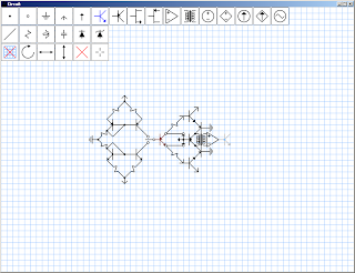
What good is sleep anyway? The top buttons now work as far as placing parts goes. The rotate and flip buttons also work. The light gray ghost shows what will happen if you click. The flip buttons light up to tell you if they're on. An orientation indicator on the rotate button would be nice too. It's possible to place parts, but not to edit them.
The buttons still don't interact, and I've thought about it some. Button movement is not as important as part placement and editing, so it's bumped down on the list to the end right after the new element color picking (where do you think that red transistor was supposed to come from?).
Tuesday, May 18, 2010
Monday, May 17, 2010
Progress for 10-5-17
There is a button class that handles some collision detection (no reaction) and all its graphics details. With support inside main, it can be moved (right now only the grid button is supported). The only buttons there that works is the grid button. There are display lists for 16 1-point components and 5 2-point components, all shown in the screenshot. The circuit shown is the same as before; hardcoded using the single-point component class. That class has no provisions for interacting with the user. Those will probably be handled in main in a general fashion. Should probably add a standard cursor button to switch back from deleting. Next up:
- Make those buttons interact with each other.
- Make it possible to add components using the buttons.
- Make it possible to edit components.
- Create a button configuration file.
- Screenshot support with provisions for existing files.
- Schematic file format.
- No windows API here. It will load and save from hardcoded filenames.
Betron I Schematic
This is all hardcoded, and the text was added in paint, but everything else was generated by software. The code looks something like
testNode->setList(NPN);
testNode->setPos(19,20);
testNode->draw();
testNode->setList(NPN);
testNode->setPos(19,20);
testNode->draw();
for each component, so It's pretty straightforward how this can be generalized into lists. Right now two-point components are handled with the one-point component class, but only because the two-point class doesn't yet exist. For the same reason, lines are handled with GL_LINES.
The whole thing actually took an hour or so to type out, and much of that time was devoted to matching grid points to points in the schematic in my notebook. That will not be a problem when the program has an interface. The main thing to note here is how sexy the schematic looks.
The whole thing actually took an hour or so to type out, and much of that time was devoted to matching grid points to points in the schematic in my notebook. That will not be a problem when the program has an interface. The main thing to note here is how sexy the schematic looks.
The circuit itself is fairly straightforward. The left side is two current mirrors. The red transistor is the DUT. depending on its type, one of the the current mirrors supplies a small current to the base, and then current at the collector can be measured via the collector voltage. There is a fixed conversion fact from the difference between collector voltage and supply voltage and the transistor beta given by
(thank you, LaTeX) where alpha_m, Vs, and VBE are for the current mirrors, and Vs is the total voltage from the positive rail to the negative rail.
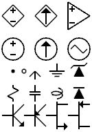
Circuit Symbols
Dependent Voltage Source, Dependent Current Source, Op-Amp
Indie Voltage Source, Indie Current Source, AC Voltage Source
Node, Open Circle, Supply Arrow, Ground, Zener Diode
Resistor, Capacitor, Inductor, Diode
NPN, PNP, NMOS, PMOS
Maybe add Transformer, Potentiometer, Variable resistor, a couple more grounds
These are all coded straight in opengl. The plan is to make the code sufficiently general that I can add any amount of additional components easily in the future. That might mean making each buttons for each component and dockable entity that can be somehow enabled and disabled. That way adding a new component is just a matter of adding a new buttons, telling it what type of component it's looking at (2-point or 1-point), and showing it the display list.
Sunday, May 16, 2010
This is how it's done
This is all hardcoded, but it's all coded in such a way that it's straightforward to generalize into lists of objects. That same generalization will make it possible to extend lines a little bit so the look nicer at edges (look at the emitters of the transistors here). Some may say that resistors should have more than just the one notch. The whole aesthetic here depends on elements being square on the grid. Don't ask me how I'm going to handle inductors.
Saturday, May 8, 2010
Plans for the Future
Summer's coming up, and that means full time development on Limit Quest. Before that, though, I'm gonna want a week or so to cool off from this past semester. I might also take that time to start thinking about game programming again with a remake of Cells using everything I've learned about game making. My goals are to make it look more polished, improve some really annoying things in the interface (for example: it's possible to resume the game from the main menu, but not obvious; I just had to guess and hope I was right.), and maybe make a nicer tutorial. I can apply new programming techniques to make the game much more compact and elegant.
Mainly for my own benefit before I forget, here's a list of some things to do:
Mainly for my own benefit before I forget, here's a list of some things to do:
- Add resume menu option
- Improve key repeat speed issue
- Mouse interaction
- Add a high score table
- Make checking give some indication of what or how much is wrong. As it stands, failing on a fully locked board basically means starting over. Maybe have options.
- Come up with a more elegant solution than the reset button. Autodetect locked board and shuffle? Sudden Death Mode (this may well be a luck thing and a bad idea)
- Add bitmap fonts
- Better tutorial
- Get rid of that console, add a title to the window, make an icon for the game
- Gameplay options: Color/Grayscale, Numbers/Colors/Both, Legend on/off
Subscribe to:
Comments (Atom)


